Stay updated with Zhuoyan's latest developments, including company news, technological breakthroughs, industry insights, and information about our R&D collaborations and recognized achievements.
Desulfurization equipment operates under demanding chemical and thermal conditions, particularly when exposed to corrosive reaction media and high-temperature process streams. Selecting an appropriate anti-corrosion coating requires consideration of the chemical composition, operating temperature, substrate material, equipment structure, and required coating thickness.
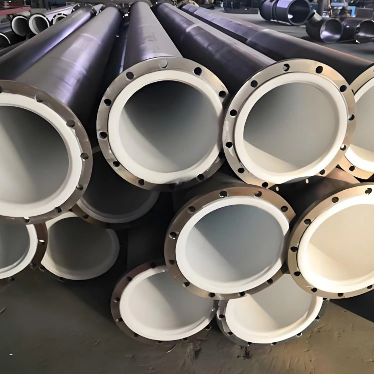
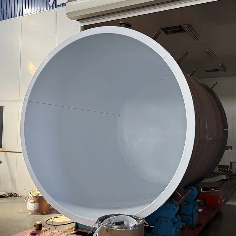
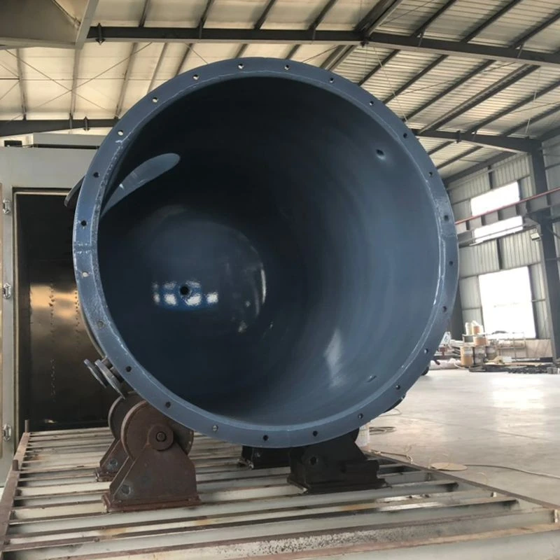
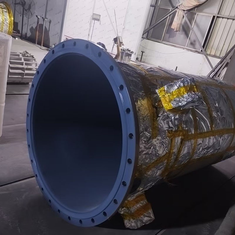
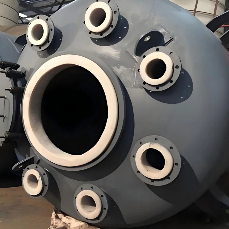
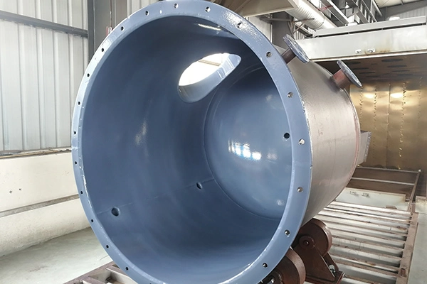
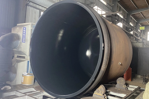
Common coating options for industrial anti-corrosion applications include PFA, FEP, ETFE (F40), and HALAR (F30). The appropriate material and application method depend on the specific equipment configuration and service conditions. For wet desulfurization condensers, special attention is required at flange sealing surfaces, tube plates, internal grids, and bottom U-shaped acid tanks, where coating uniformity, complex geometry, and thermal exposure can affect long-term performance.
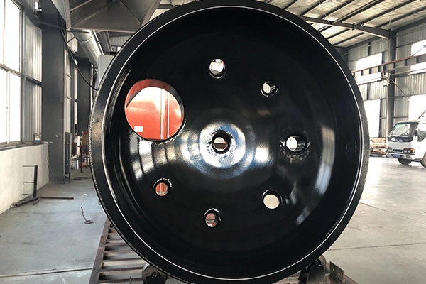
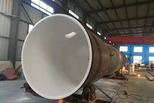
The specified maximum workpiece dimensions for spraying are up to Ø3.8 m × 3.8 m × 8.2 m. The suitability of these dimensions should be confirmed against the actual workpiece geometry and the requirements of the selected coating process.
Before selecting an anti-corrosion coating for desulfurization equipment, the operating environment should be clearly defined. The following information is particularly important:
These conditions provide the basis for evaluating chemical compatibility, coating selection, application requirements, and inspection criteria. A coating material should not be selected solely by its general corrosion resistance; its suitability must be confirmed for the actual chemical composition and operating environment.
Several fluoropolymer coating materials are used in industrial corrosion-protection applications. Each has specific material characteristics, and the appropriate option should be determined according to the process medium, temperature, substrate, and equipment configuration.
| Coating Material | Application Considerations |
|---|---|
| PFA | Considered for applications requiring chemical resistance and a fluoropolymer-coated internal surface, subject to the specified service conditions. |
| FEP | Used for selected corrosion-protection applications where the material properties and operating limits meet the process requirements. |
| ETFE (F40) | Used for specified coating applications, including selected condenser components, according to the required temperature and chemical conditions. |
| HALAR (F30) | Used for selected industrial anti-corrosion coating applications. Its suitability must be confirmed for the particular chemical medium and operating environment. |
The corrosion resistance and temperature performance of these materials are not identical. Chemical composition, concentration, exposure duration, coating construction, and the conditions experienced by individual equipment components should all be reviewed before the coating system is finalized.
The specified anti-corrosion coating thickness can range from 0.3 mm to 1.5 mm, depending on customer requirements and the selected coating system. The required thickness should be defined before production and verified using an inspection method appropriate to the coating and equipment design.
Uniformity is particularly important around openings, flange sealing surfaces, and other geometrically complex areas. Excessive coating accumulation or uneven application can interfere with the intended component dimensions and sealing arrangements. The finished coating should meet the agreed thickness and acceptance criteria.
Substrate materials considered for industrial anti-corrosion applications include:
The appropriate surface preparation and application procedure depend on the substrate material. Not every coating process is suitable for every substrate, so compatibility, surface preparation, and adhesion requirements should be evaluated for the specific combination of coating and base material.
A controlled spraying process is essential for achieving the specified coating condition. The exact procedure depends on the selected material, substrate, equipment geometry, and manufacturing requirements.
Process parameters should be controlled according to the selected material and substrate. Particular attention should be given to coating uniformity and the prevention of coating runs around holes, flange faces, and other critical areas.
The listed coating colors include:
Color availability should be confirmed for the selected coating material and application requirements.
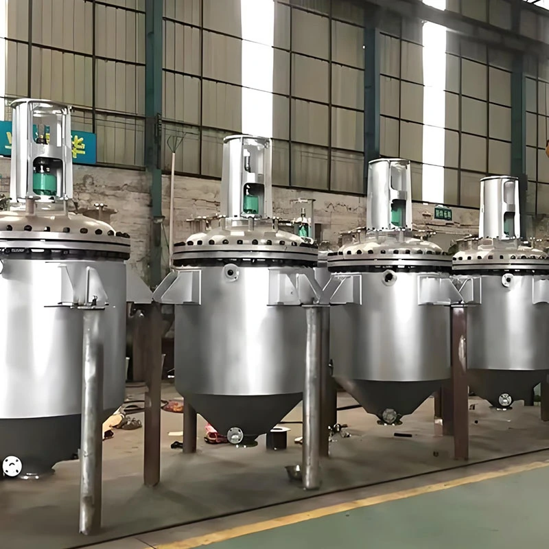
Wet desulfurization condensers may be configured vertically or horizontally. Their internal structures and operating conditions differ, so coating material selection, thickness requirements, and construction details should be assessed for each component rather than applied uniformly across the entire condenser.
A vertical wet desulfurization condenser is described as having four principal sections: the top cover, upper tube plate, lower tube plate, and bottom U-shaped acid tank. Each section has different contact-temperature and coating requirements.
| Component | Specified Coating | Coating Thickness | Stated Contact Temperature | Key Considerations |
|---|---|---|---|---|
| Top cover | ETFE (F40) or HALAR (F30) spraying | 1 mm | Not exceeding 120°C | Keep the flange sealing surface free from coating runs and maintain uniform coating thickness. |
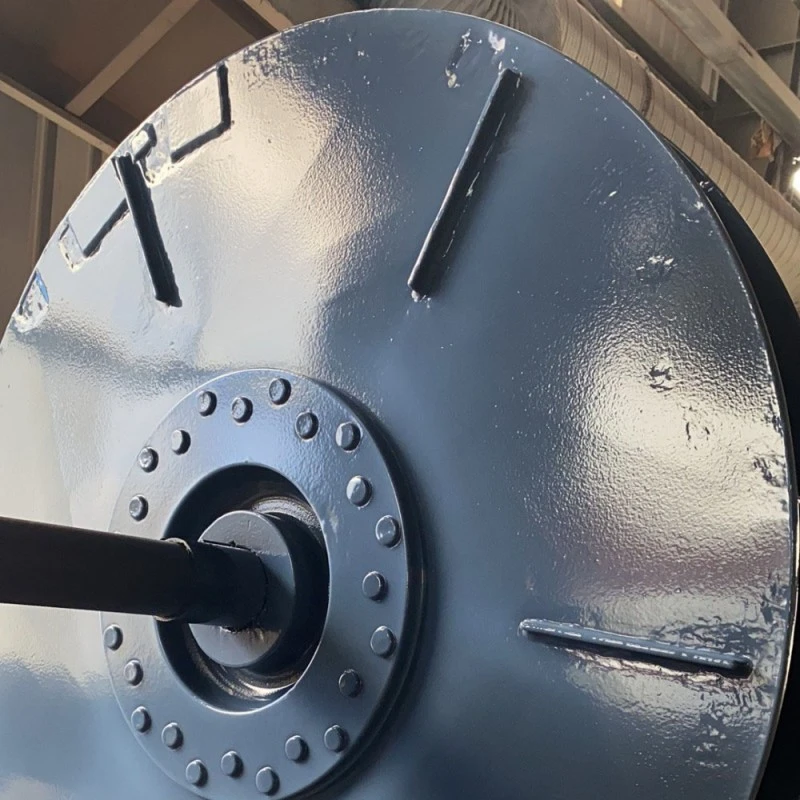
| Upper tube plate | ETFE (F40) or HALAR (F30) spraying | 1 mm | Not exceeding 150°C | Prevent coating runs around the holes and maintain uniform coverage across the plate. |
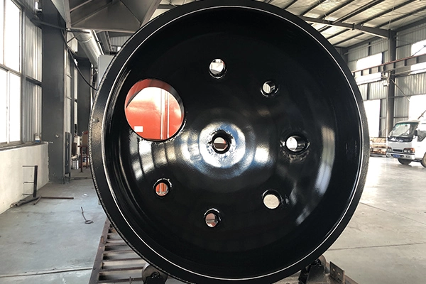
| Lower tube plate | PFA spraying | 1 mm | Approximately 260°C | Pay particular attention to the holes, avoiding coating runs and uneven thickness. |
| Bottom U-shaped acid tank | PTFE lining or PFA spraying | To be confirmed for the selected process | Maximum service temperature stated as up to 290°C | Complex geometry and demanding thermal conditions require a specific construction and protection review. |
ETFE (F40) or HALAR (F30) spraying is specified for the top cover, with a coating thickness of 1 mm and a stated contact temperature not exceeding 120°C. The flange sealing surface requires particular attention because coating runs or excessive accumulation can affect the sealing interface. The coating should be uniform across the specified surface.
The upper tube plate is specified for ETFE (F40) or HALAR (F30) spraying, with a thickness of 1 mm and a stated contact temperature not exceeding 150°C. The holes require careful application control to prevent coating runs and maintain the intended geometry.
PFA spraying is specified for the lower tube plate, with a thickness of 1 mm and a stated contact temperature of approximately 260°C. Because the plate contains multiple holes and transitions, coating uniformity and control of material accumulation are important inspection considerations.
Two construction options are identified for the bottom U-shaped acid tank: PTFE lining and PFA spraying. The tank's geometry can make either process challenging, while the stated maximum service temperature can reach 290°C.
The supplied design information specifies a 300–500 mm acid-resistant brick layer over the coated surface to help limit direct thermal exposure and impact. Given the demanding temperature conditions, the coating material, protective layer, interface details, and complete construction should be verified against the actual process requirements before the design is finalized.
A horizontal wet desulfurization condenser is described as having five principal sections: the top cover, demisting grid plate, three-section tube section, packing grid plate, and bottom U-shaped acid tank.
| Component | Specified Coating | Coating Thickness | Stated Contact Temperature | Key Considerations |
|---|---|---|---|---|
| Top cover | PFA spraying | 1 mm | Approximately 180°C | Confirm coating uniformity and the condition of relevant connection surfaces. |
| Demisting grid plate | PFA spraying | 1 mm | Approximately 180°C | Check coverage across the grid structure and its complex geometries. |
| Three-section tube section | PFA spraying | 1 mm | Approximately 200–250°C | Verify coating suitability for the stated temperature and the actual process medium. |
| Packing grid plate | To be confirmed | To be confirmed | To be confirmed | Determine the coating and operating requirements from the component's specific service conditions. |
| Bottom U-shaped acid tank | PTFE lining or PFA spraying | To be confirmed for the selected process | Maximum service temperature stated as up to 280°C | Review the construction method, complex geometry, and required thermal protection. |
PFA spraying is specified for the top cover and demisting grid plate, with a coating thickness of 1 mm and a stated contact temperature of approximately 180°C. The demisting grid plate contains more complex surface geometry than a flat plate, making consistent coverage and inspection particularly important.
The three-section tube section is specified for PFA spraying at a thickness of 1 mm, with a stated contact-temperature range of approximately 200–250°C. The coating specification should be assessed against the actual process medium and operating cycle, including temperature variations during operation.
The packing grid plate is identified as one of the five principal sections of the horizontal condenser, but a specific coating material, thickness, and contact temperature are not provided in the supplied information. These parameters should be confirmed according to the component's actual operating conditions and corrosion-protection requirements.
PTFE lining and PFA spraying are both identified as potential construction methods for the bottom U-shaped acid tank. The component's complex shape can make coating application or lining installation difficult, and the stated maximum service temperature can reach 280°C.
The supplied design information specifies a 300–500 mm acid-resistant brick layer over the coated surface to help reduce direct thermal exposure and impact. The suitability of this protective arrangement should be assessed as part of the complete equipment design, including the actual temperature profile and the requirements of the coating or lining system.
The temperature values listed for individual condenser sections are application-specific design inputs. They should not be interpreted as universal operating limits for PFA, FEP, ETFE, HALAR, or PTFE-lined equipment.
The actual suitability of a coating or lining depends on several factors:
Before selecting a coating material or approving a condenser design, the stated temperatures and construction details should be checked against the actual process conditions. Where a component operates near a material's specified limit, the complete assembly and any additional protective measures require particular attention.
Anti-corrosion spraying for desulfurization equipment requires coordinated consideration of coating material, substrate, thickness, equipment geometry, operating temperature, and chemical compatibility. PFA, FEP, ETFE (F40), and HALAR (F30) provide different material options for selected industrial applications, but the final choice must be based on the actual service conditions.
Wet desulfurization condensers require component-by-component evaluation because top covers, tube plates, grid structures, and bottom U-shaped acid tanks may experience different temperatures and present different coating challenges. Particular attention should be given to flange sealing surfaces, holes, complex geometries, and components exposed to demanding thermal conditions.
Clear operating data, an appropriate coating process, defined inspection criteria, and verification of the complete construction provide the basis for a suitable anti-corrosion solution. Final coating specifications and protective arrangements should be confirmed against the equipment design and actual process requirements before manufacturing and operation.